The Plan Routes tool determines how a fleet of vehicles can visit a set of stops in the least amount of time.
Most people are familiar with single-vehicle navigation, which takes a set of stops and finds the quickest route for one vehicle to visit them. Some single-vehicle navigation tools can optimally rearrange the stop order to prevent the route from backtracking and crisscrossing itself, which ultimately minimizes the overall travel time or distance.
Plan Routes is similar, but instead of routing a single vehicle at a time, it routes many vehicles at once. Furthermore, it determines how the stops should be assigned among the various routes and the best order in which the routes should visit the stops.
Plan Routes offers the following benefits:
- It simplifies the otherwise complicated job of plotting routes for a fleet of vehicles.
- It generates efficient routes, which saves time and resources for the entire organization and limits fuel usage and vehicle pollution.
- It stores the results in your portal, which makes sharing routes with drivers more efficient.
Balancing work
Max number of stops per vehicle and Max time per vehicle (minutes) can be used to balance the workload between vehicles in the fleet you are routing.
The following examples demonstrate the effects of limiting the maximum stops per vehicle or the total time per vehicle. In all examples, there are six stops and two routes, which start at the same location.
 | Balanced travel times and stops per route: The stops are more or less uniformly spread apart, so setting the maximum stops per vehicle to evenly distribute the workload results in routes that are roughly the same duration. |
 | Balanced stops per route but unbalanced travel times: Five of the six stops are clustered near the starting location, but one stop is set apart and requires a much longer drive to be reached. Dividing the stops equally between the two routes causes unbalanced travel times. |
 | Unbalanced stops per route but balanced travel times: The stops are in the same location as the previous graphic, but by increasing the maximum stops per route and limiting the total travel time per vehicle, the travel times are balanced. |
Starting and ending locations
The starting and ending locations of routes or vehicles are as important as the locations of the stops they will visit. By knowing all these locations, the tool can assign the stops to the nearest vehicles to reduce overall travel times. In some cases, the Plan Routes tool names the output routes based on where they begin and end.
Several parameters can be used in combination to set the start and end points: Start layer, Return to start, End layer, Start layer route ID field, and End layer route ID field.
One starting point and returning to start
The most common problem to set up is one where all routes start and end at the same location. For example, a charitable organization seeking to efficiently deliver donations to people in need parks its delivery vans at a single warehouse. On delivery days, volunteers load the vans, which then spread out to various stops to deliver the packages. The vans return to the warehouse after they complete their deliveries.
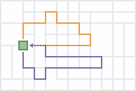
The start and end locations are set up as follows:
- Start layer—A layer with one point.
- Return to start—Enabled.
One starting point and one ending point
Sometimes all routes start at one location and end at another. For example, when planning routes for several passenger vans that will leave a depot, pick up spectators from their homes, and take them to an event, such as a concert, the depot is specified as the single starting location, and the venue of the event becomes the single ending location.
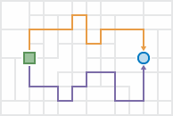
The start and end locations are set up as follows:
- Start layer—A layer with one point.
- Return to start—Not enabled.
- End layer—A layer with one point.
Because all drivers start and end at the same two locations, it is assumed any driver can drive any route, so the output routes are given names such as Route 1 and Route 2.
Many starting points and returning to start
For this problem type, each route starts from a unique point, visits its assigned stops, and finishes at the place where it began. For example, inspectors may start the day at their homes, go to various inspection sites, and return home at the end of the day.
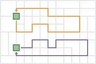
The start and end locations are set up as follows:
- Start layer—A layer with multiple points.
Note:
Each route is always assigned its own starting point for this problem type. If a subset of routes start at the same location, add their starting points next to or on top of each other to ensure that each route has its own corresponding starting location.
- Start layer route ID field—The ID field in the start layer that uniquely identifies the routes or drivers. It can be a route number, the driver's name, or some other unique name.
- Return to start—Enabled.
Since the routes and their drivers start at unique locations, the ID field of the start layer must be specified. The output route names are automatically generated to be the same as the values in the ID field so the routes can be assigned and delivered to the appropriate drivers.
Many starting points and one ending point
Each route starts from a unique point, visits its assigned stops, and converges with the other routes at a single ending location for this problem type. For example, an airport shuttle service picks up passengers from different hotels and drives them to the airport.
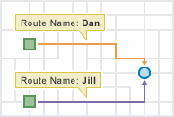
The start and end locations are set up as follows:
- Start layer—A layer with multiple points.
Note:
Each route is always assigned its own starting point for this problem type. If a subset of routes start at the same location, add their starting points next to or on top of each other to ensure that each route has its own corresponding starting location.
- Start layer route ID field—The ID field in the start layer that uniquely identifies the routes or drivers. It can be a route number, the driver's name, or some other unique name.
- Return to start—Not enabled.
- End layer—A layer with one point.
Since the routes and their drivers start at unique locations, the ID field of the start layer must be specified. The output route names are automatically generated to be the same as the values in the ID field so the routes can be assigned and delivered to the appropriate drivers.
One starting point to many ending points
In the one-to-many problem type, all routes start from one point, visit their assigned stops, and end at unique locations. For example, a utility company needs to hang shutoff warning tags on the doors of delinquent customers. Employees are offered extra pay to hang the tags on their way home from work.
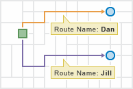
The start and end locations are set up as follows:
- Start layer—A layer with one point.
- Return to start—Not enabled.
- End layer—A layer with multiple points.
Note:
Each route is always assigned its own ending point for this problem type. If a subset of routes end at the same location, add their ending points next to or on top of each other to ensure that each route has its own corresponding ending location.
- End layer route ID field—The ID field in the end layer that uniquely identifies the routes or drivers. It can be a route number, the driver's name, or some other unique name.
Since the routes and their drivers end at unique locations, the End layer route ID field parameter is visible and must be specified. The output route names are automatically generated to be the same as the route ID values so the routes can be assigned and delivered to the appropriate drivers.
Many starting points to many ending points
In some planning scenarios, each route has unique starting and ending locations. For example, school bus drivers in a rural school district park their buses at their homes at night. In the morning, they start their routes from home, pick up students, and drop them off at schools across the district.
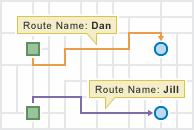
The start and end locations are set up as follows:
- Start layer—A layer with multiple points.
Note:
Each route is always assigned its own starting point for this problem type. If a subset of routes start at the same location, add their starting points next to or on top of each other to ensure that each route has its own corresponding starting location.
- Start layer route ID field—The ID field in the start layer that uniquely identifies the routes or drivers. It can be a route number, the driver's name, or some other unique name.
- Return to start—Not enabled.
- End layer—A layer with multiple points.
Note:
Each route is always assigned its own ending point for this problem type. If a subset of routes end at the same location, add their ending points next to or on top of each other to ensure that each route has its own corresponding ending location.
- End layer route ID field—The ID field in the end layer that uniquely identifies the routes or drivers. It can be a route number, the driver's name, or some other unique name.
Since the routes and their drivers start and end at unique locations, the start and end layer ID field parameters are visible and must be specified. The values in the start and end layer ID fields must match each other exactly. The output route names are automatically generated to be the same as the route ID values so the routes can be assigned and delivered to the appropriate drivers.
Route layers
Creating route layers is useful if you want to share the individual routes with other members of your organization or to further configure the routes using the Directions pane in Map Viewer. The route layers use the name provided for the feature layer as a prefix, and the route name generated as part of the analysis is added to create a unique name for each route layer.